SciMed
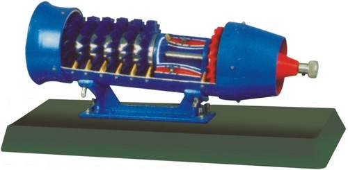
Gas Turbine / Turbojet Engine Cutaway Model — Axial Flow Compressor, Combustion Chamber, Turbine, 17"
Gas Turbine / Turbojet Engine Cutaway Model — Axial Flow Compressor, Combustion Chamber, Turbine, 17"
Impossibile caricare la disponibilità di ritiro
Cutaway sectional teaching model of a gas turbine / turbojet jet engine — light-and-strong metal construction reveals every stage of jet propulsion: air intake, 2-stage axial-flow compressor, fuel supply, combustion chamber, turbine rotor, jet thrust nozzle, and exhaust. Printed schematic diagram on the base labels each component + shows the Brayton cycle (isobaric combustion + isentropic compression/expansion). 17" long × 6" high — desktop demonstration size. For aerospace engineering, mechanical engineering, physics, and STEM education. $599.99 direct.
Components visible (in flow order)
- Air intake — cowl showing airflow direction into compressor
- Axial flow compressor (Stage 1) — rotor + stator blades compressing incoming air ~4-8× ambient pressure
- Axial flow compressor (Stage 2) — second stage compressing to ~15-30× ambient (typical turbojet)
- Fuel supply line — kerosene / JP-4 injection into combustion chamber
- Combustion chamber — continuous combustion of compressed air + fuel at ~1500°C
- Turbine rotor — expanding hot gas drives turbine that powers the compressor via central shaft
- Jet thrust nozzle — remaining hot gas exits at high velocity, creating thrust
- Exhaust — reduced pressure/temperature exit to atmosphere
Teaching applications
- Aerospace engineering — jet propulsion, gas turbine theory, Brayton cycle
- Mechanical engineering — turbomachinery, compressor + turbine design
- Thermodynamics — Brayton cycle analysis, isobaric/isentropic processes
- Fluid mechanics — compressible flow, choked nozzle, subsonic + supersonic transitions
- Power engineering — gas turbine power generation (industrial + utility)
- Aviation training — pilot ground school + AMT (Aircraft Maintenance Technician) training
- Aerospace museums + displays
Specifications
| Configuration | Turbojet with axial-flow 2-stage compressor + single-stage turbine |
|---|---|
| Construction | Light-weight metal (steel + aluminum alloys) |
| Cutaway view | Section cut revealing all internal components |
| Base | Mounted on demonstration base with printed schematic + component labels |
| Dimensions | 17" long × 6" high (desktop demonstration size) |
| Weight | ~4-6 kg |
| Power | Static display model (does NOT actually run) |
| Warranty | 1-year against manufacturing defects |
Best for
- Aerospace engineering departments (undergraduate + graduate teaching)
- Mechanical engineering programs
- Aviation training academies + AMT schools
- Aerospace museums + interactive displays
- ITI + polytechnic aeronautics courses
- University thermodynamics + fluid mechanics teaching
- Corporate training (jet engine OEMs — GE, Pratt & Whitney, Rolls-Royce)
- International aerospace + defense training programs (via DDP)
Buying for an aerospace program or training school?
- Volume pricing on 5+ orders — multi-lab university builds, aviation academy fleets
- Net-30 invoicing for verified schools, universities, training programs
- SAM.gov compliant for federal + military aviation training (Navy, Air Force, VA)
- Bundle with 4-Stroke Petrol Engine + 4-Stroke Diesel + Steam Engine for complete Engine Teaching Set
- Instructor's guide with Brayton cycle worked examples included on request
- International DDP shipping — aerospace training growth markets (India, GCC, LATAM, SE Asia)
FAQ
Does this actually run?
No — this is a STATIC CUTAWAY MODEL for teaching, not a functional jet engine. Students see all internal components (compressor blades, combustion chamber, turbine, nozzle) in their spatial relationship + flow order. For running gas turbine demos, look at industrial "cutaway trainers" ($15K+).
What can students learn from a static model?
Brayton cycle analysis (temperatures + pressures at each station 1→5), spatial relationships (why the turbine is downstream of combustion, how it drives the compressor via shaft), component identification (blade rows in axial compressor + turbine, combustion chamber geometry), and flow-path visualization (air enters cool + slow, exits hot + fast).
Is this a real jet engine cutaway or a teaching representation?
Teaching representation — proportions + component visibility are optimized for education, not exact scale of a real engine. For real cutaway engines (retired GE / P&W / Rolls-Royce engines cut open), aerospace museums + military bases sometimes have those but they're not commercial equipment.
User Manual (PDF)
Download the User Manual (PDF)
Browse all manuals by category at scimedstore.com/pages/user-manuals. Need a digital or printed copy, or have a question? Email sales@scimedstore.com.
Share